(AKA International Hydraulics Inc)
7700 St. Clair Avenue
Mentor, Ohio 44060
Ph 440-951-7186 Fax 440-951-1071
|
(AKA International Hydraulics Inc) 7700 St. Clair Avenue Ph 440-951-7186 Fax 440-951-1071 |
|
||||||||||
 |
84JM | ISO 9001 |
ANSI |
|||||||
Do's and Don'ts for High Amp, Wide Trace PCB Design with IHI Wave Solderable Connectors - Heat In and Heat Out.
Do read Standard IPC-2152 Standard for Determining Current Carrying Capacity of Printed Circuit Boards- it has been updated in 2009 with current charts for copper PCB traces. Then bear in mind that higher currents than the conservative IPC-2152 standard can be achieved with engineering creativity and testing.
Do consider that in still air, heat flows much better through the board thickness than from the surface of the board to air. So much so that IPC-2152 (in still air or vacuum) now says that internal traces enjoy the same the heat transfer to the board as external ones.
Do consider use of air flow to enhance the heat dissipation of PCB traces particularly for continuous current applications where the thermal capacity of the PCB will not help the long term thermal stability.
Even air moving at 1-4 MPH (walking speed) will make a huge difference to the PCB-to-air heat transfer. Temperature rise can be cut in half at 3.5 MPH. If averse to fans, a passive vertical convection flow system ("chimney" effect) can reach useful air speed and heat transfer levels but need comparatively large vent openings vs. fan forced.
Do consider that vertical surfaces are more conducive to air flow than horizontal ones.
Do use the heaviest copper thickness (weight in ounces per square foot) that the cost objectives can stand. The copper cross section and length is the source of heat from the formula:
Watts of heat = Resistance* (Current)^2
Current is the goal so reduce the resistance by using the thickest, widest, and shortest copper trace you can. The more commonly used weights of copper are lower cost but thicker weights may be required depending on the test results. Consider a larger board to help distribute heat and larger traces in place of a more expensive thicker copper board thickness. You may need larger and thicker if currents dictate it.
Do avoid thin PCB substrate materials. A trace on a thinner board heats up more than thicker ones for the same current. The trace rise on a .07" board can be 50% that of a .010" board. However the benefit of increasing thickness further is rather less significant. In still air, the majority of the trace heat transfers to the board substrate not the air so the board matters. In a moving air scenario, the heat can move to the air much more readily but why skimp on board thickness?
Do recognize that FR series board materials (phenolic/epoxy resin) while economical do not have great thermal conductivity. Consider Polyamide material for a up to 25% reduction of heat rise and even better, special resin filled with high conductivity media to achieve more than 50% reductions in heat rise. Glass fiber filling provides the most dimensional stability - important to reduce expansion differential stress fatigue issues.
Do use an "oversize" wire connector such as the IHI range of wave solderable PCB wire connectors. "Chunky" UL type wire connectors have a substantial mass of aluminum to hold the wire. Made to UL standards for wire secureness and thermal stability, dissipating heat to free air from a large surface area (5 sides of a cube of aluminum, 3-4 of which are vertical faces). Aluminum has 50% better conductivity than brass. The B2 series staple is pure copper maintaining a copper current path from wire to trace.
Do use copper planes in the board (multilayer), or on the opposite side of the board to help sink heat away from the high current traces. Copper planes can reduce heat rise of a high amp trace by more than half.
Do expand the width of high amp traces wherever there is room to do so. Form follows function. The trace should have the most width that it can along its path, even if it looks oddly shaped. Any extra copper will help the total heat transfer from the main current path.
Do recognize that wider high current traces can transfer heat to air more efficiently than narrower ones. Especially important in moving air heat transfer.
Do remember that two equal traces on the same route on opposite sides of the board will not handle twice the current as one such trace. The heat is trapped in the sandwich and so doubles the heat in that location. Running the traces along differing routes can enable each trace to enjoy the cooling path individually and thereby come closer doubling the current as hoped.
Do use shunts to bridge an area where there has to be a "squeezed" trace width.
LugsDirect.com can provide 100 amp stock shunts / jumper for short distances that are wave solderable.
(Click here for an example layout of current shunting between two B2A-PCB or B2C-PCB terminals)
.jpg)
100Amp current shunt / jumper / zero ohm link
Do remember that copper will increase in resistance with temperature which increases the I2R heat wattage. A copper shunt or bridge can avoid such a hot spot generating heat. Very short narrowed traces can be relatively benign if the adjacent copper can be increased significantly to compensate and mitigate the heat rise at the tight spot. Long narrowed traces are bad as the temperature will rise more, the further from the wider part of the trace, resulting in a hot spot half way along the long narrowed trace. Like fuse wire, it melts first in the middle, furthest from the cooler end caps. A vertical copper bus strip with numerous solderable legs may be the best answer to long tight runs.
Do use vias (those plated through holes from one copper plane to another) to sink heat to plane areas which are cooler or use to share the current flow to both sides of the board or inside the board.
Do remember that IPC-2152 determined that the inside traces can handle as much current as outside ones. Old research discounted the current by 50% but the new charts treat inside as outside ones. IPC-2152 is tested only in static air. In a moving air situation it would be fair to assume the outside traces will dissipate heat to the moving air faster than the inside traces insulated by a polymer jacket.
Do minimize breaks in copper planes especially that are near high current traces to avoid breaking the heat flow path that such traces provide. The polymer material of the board is not good at conducting heat in the same plane so the copper planes and connecting vias are paramount.
Do use overlapping copper planes where breaks are needed to mitigate the thermal resistance at the gap.
Do rely on convection and conduction to dissipate heat. If the board gets hot enough to radiate meaningful heat, it is too probably already way too hot for most applications.
Do keep in mind that after moving the heat way from the hottest spots on the board itself, the heat has to go somewhere else to maintain heat flow from the hot spots. Consider the use of finned heat sinks, current shunts, highly conductive case materials like aluminum and air vent orientation to assist hot air to leave the area.
Finned aluminum heat sinks can be used anywhere there is room including on insulating material and adjacent regions that are sinking heat from the main hot spots.
Do note that when traces are dip soldered that they lose some of their integrity with the polymer substrate and heat flow is thereby reduced. Do test PCB's processed the way they will be in production. Delamination of traces is a hard thing to predict but will reduce the amp capacity of a PCB trace.
A substantially delaminated trace can reduce heat flow into the board by up to 50%.
Do build thermal sensing into your design to allow automatic rollback of current (=heat) or a total cut out if temperatures rise over limits for whatever reason. Extremes of weather and other impediments to moving heat off the board can and will happen.
Do recognize that component and board life will be shortened by extremes of temperature and thermal cycling. However, one may be comforted by the knowledge UL /CSA approved aluminum PCB solderable wire connectors have already passed a severe 500 cycle thermal /conductivity stability test at highly elevated current flows (UL486 B).
A life rule of thumb for printed circuits is that every 10 Degrees C increase in working temperature, will halve the life of the PCB assembly. So just upping the temperature is a low life way to squeeze more amps into a small PCB.
Do make a quality product that will last. Find the lowest cost 'right' way. Do give homage to the many hidden issues that can deteriorate a marginal design and make it a low life design. High current stress testing with current cycling is a good way to artificially age your project to determine weak spots or fundament errors before mass production. Keep in mind that so much more is being asked of lightweight PCB that the an all metal electrical panel bus system with lower current densities, so test, test and test.
Do not rely on solder on a trace to help the performance of copper traces though it may help the conductivity of filled vias. Solder has a low thermal and electrical conductivity and the dip soldering thermal shock delamination factor is a detriment to the heat flow into the substrate.
Do not rely solely on the strength of solder joints mechanically, especially at higher board temperatures. Solder has a low creep strength, decreasing with temperature which means heavy hanging cables from PCB wire connector may need additional weight support. IHI PCB solderable lugs are constructed to have one or two substantial through-the-board legs to ensure a both a mechanical bond with the PCB as well as the soldered joint.
For samples of solderable PCB wire connectors to test your high amp application please email sales@LugsDirect.com.
References, acknowledgements and recommended reading: IPC Current Carrying Capacity Task Group (1-10b), IPC Printed Board Design Committee (1-10), IPC-2152, MIL-STD-275, IPC-D-275, IPC-TP-117, Robert Kollman (TI) Constructing your Power Supply - Layout Considerations. Mike Joupi & Paul Cooke of Coretec, Brad Suppanz of CircuitCalculator Blog, and many other selfless individuals who share their knowledge writing articles and blogging on the web.
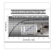
The chart below is a compilation of various published sources for current ampacity of bare copper conductors. It is interesting that NEC /UL specifies a 1000 amps per square inch as the recommended copper bus current density in typically heavier industrial / commerical applications but as copper cross sections diminish the practical current density is able to increase significantly. This is good news for printed circuit board designers as surprisingly high currents may be carried on copper traces that are much lower in cross section than one would expect.
At first it seems hard to reconsile the conventional current densities with the Printed Circuit Board current densities but a look a the various ampacity data on a log-log chart shows a distinct and somewhat continuous trend considering varying aspect ratios of square, rectangular, flat and round wire/bus.
Ampacity is measured in heat rise so naturally the amount of cooling from surrounding air or polymer board is a major factor in enabling the condictor to stay cool. The ratio of exposed surface area to conductor area increases as the conductor decreases in size.
Consequently, increasingly higher current densities may be obtained with acceptable heat rises as the conductor size becomes smaller. An incredible density of over two million amps per square inch is possible at failure for a sigle copper whisker of .0003" diameter.
Copyright © 2007-2026 IHI Connectors®, Ohio - All Rights Reserved
The IHI linked logo, IHI Connectors and IHIConnectors.com are registered trademarks of International Hydraulics Incorporated. CAGE / NCAGE Number 7RPR4